

Article Summary: Pneumatic actuators are becoming an increasingly important part of industrial valve automation as manufacturers move from manual flow control toward faster, repeatable and centrally managed production systems. Installed between the control system and the valve, a pneumatic actuator converts compressed-air energy into mechanical movement that opens, closes or positions a valve. This makes the actuator a critical link between PLC, DCS or other automation commands and the physical movement required to control water, steam, gases and process liquids. This article examines how pneumatic actuators support industrial valve automation, how single-acting and double-acting designs differ, why fail-safe positioning matters, how actuators interact with ball valves, butterfly valves, angle seat valves and other process valves, and what engineers should evaluate when designing automated fluid control systems.
Industrial fluid control has changed significantly as factories have become more automated. In traditional systems, operators might manually open and close valves according to production requirements. That approach can still be suitable for simple processes, but it becomes increasingly difficult to manage as production lines become larger, faster and more complex.
An automated production system may contain dozens or even hundreds of valves controlling water, steam, compressed air, cleaning solutions, gases or process liquids. If every valve requires manual operation, response times become slower and process consistency becomes more dependent on individual operators.
Pneumatic actuation provides a different approach. Instead of requiring an operator to physically turn a valve handle, a control signal can operate a pneumatic actuator. The actuator then moves the valve to the required position.
This relationship can be simplified as:
Automation System → Control Signal → Solenoid Valve → Compressed Air → Pneumatic Actuator → Process Valve → Fluid Control
The actuator is therefore not simply an accessory mounted on a valve. It is the mechanical execution layer that converts an automation command into physical flow-control action.

The expansion of industrial automation is creating broader demand for valves, actuators and other pneumatic components.
Grand View Research estimated the global industrial automation and control systems market at approximately USD 226.8 billion in 2025. It projects the market to increase from approximately USD 250.3 billion in 2026 to USD 504.4 billion by 2033, representing a compound annual growth rate of 10.5% between 2026 and 2033. Control valves accounted for approximately 24% of the market by component in 2025.
At the same time, the global pneumatic actuator segment generated approximately USD 7.80 billion in revenue in 2025 and is projected to reach approximately USD 12.11 billion by 2033, according to Grand View Research. The organization estimates a CAGR of 5.7% for the pneumatic actuator segment from 2026 to 2033.
| Market Indicator | Published Value | Period | Source |
|---|---|---|---|
| Global industrial automation and control systems market | USD 226.8 billion | 2025 | Grand View Research |
| Projected industrial automation and control systems market | USD 504.4 billion | 2033 | Grand View Research |
| Industrial automation market CAGR | 10.5% | 2026-2033 | Grand View Research |
| Control valve share of automation market by component | 24% | 2025 | Grand View Research |
| Global pneumatic actuator segment revenue | USD 7,803.4 million | 2025 | Grand View Research Horizon |
| Projected pneumatic actuator segment revenue | USD 12,114.6 million | 2033 | Grand View Research Horizon |
| Pneumatic actuator market CAGR | 5.7% | 2026-2033 | Grand View Research Horizon |
These figures describe general global market trends and are not sales, production or market-share figures for Zhejiang Fengdu Technology Co., Ltd.
A pneumatic actuator uses compressed air to produce mechanical movement.
In industrial valve automation, that movement is used to change the position of the valve closure element. Depending on the valve design, the movement may be linear or rotary.
For example:
A Pneumatic angle seat valve generally uses linear movement to raise or lower an internal plug.
A pneumatic ball valve typically requires approximately quarter-turn rotary movement.
A pneumatic butterfly valve also normally uses quarter-turn rotary movement.
A diaphragm valve commonly uses linear actuator movement.
The actuator must therefore be matched to the movement and force requirements of the valve.
Installing a pneumatic actuator does not automatically make every valve suitable for every automated application. The actuator must generate sufficient thrust or torque to overcome valve friction, differential pressure, sealing forces and process loads.
In an automated process, measurement and control systems can determine what should happen, but something must physically change the process.
A temperature sensor, for example, may detect that process temperature has exceeded a setpoint. A PLC or process controller can then issue a command. The pneumatic actuator receives the resulting air-control signal and moves the valve.
The physical movement of the valve changes the flow of steam, cooling water or another medium.
This creates a closed automation sequence:
A sensor measures a process condition.
The control system compares the value with a target.
The controller generates an output signal.
A solenoid valve or pneumatic control device manages actuator air.
The actuator moves the process valve.
The resulting flow change influences the process.
Because the actuator performs the final mechanical movement, actuator reliability directly influences whether automation commands are successfully executed.
Single-acting pneumatic actuators use compressed air to move the actuator in one direction and normally use a spring to return it in the opposite direction.
This architecture is especially important where the valve must move toward a predetermined position if pneumatic pressure or control energy is lost.
Depending on the system design, the spring-return action may be configured to move the valve toward:
Fail close
Fail open
Emerson's published guidance on pneumatic rack-and-pinion actuators describes spring-return construction as suitable for fail-safe applications and notes that such actuators can be assembled for fail-close or fail-open operation.
Festo safety documentation similarly describes spring-driven safety movement for single-acting pneumatic actuators, including functions in which the actuator moves a shutdown valve to a closed or open position after control air is vented.
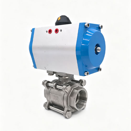
Double-acting actuators use compressed air in both directions.
Instead of relying primarily on spring force for the return stroke, pneumatic pressure moves the actuator toward both operating positions.
This architecture can provide several practical benefits:
Available pneumatic force in both directions
No large return spring required for normal movement
Useful torque characteristics for many rotary valve applications
Flexible operation for repeated opening and closing
However, loss of air supply must be considered carefully. A double-acting actuator does not inherently provide the same spring-return action as a single-acting actuator.
Emerson notes that double-acting pneumatic actuators may be used for applications requiring a fail-in-last-position function, depending on the complete control arrangement.
| Selection Factor | Single-Acting Actuator | Double-Acting Actuator |
|---|---|---|
| Air operation | Air typically drives one direction; spring provides return movement | Compressed air drives both directions |
| Spring return | Normally included | Normally not required for standard operation |
| Fail-safe capability | Can be configured for fail-open or fail-close depending on design | Requires control-system strategy if a defined failure position is needed |
| Air consumption | Air normally required for one powered direction | Air required for both opening and closing strokes |
| Typical consideration | Safety-related shutoff and applications requiring predictable spring return | Frequent bidirectional operation and applications requiring powered movement in both directions |
| Selection basis | Process safety philosophy and required failure state | Torque, control strategy and operating requirements |
The table describes general actuator architecture. Final actuator selection must be based on the actual process, valve torque or thrust requirement, air pressure and system safety analysis.
One of the most important questions in valve automation is not simply whether the valve can open and close during normal production.
Engineers must also determine what should happen when something goes wrong.
Possible abnormal conditions include:
Loss of electrical power
Loss of compressed air
Solenoid valve failure
Emergency shutdown activation
PLC output failure
Broken control wiring
The preferred valve position during such an event depends on the process.
For example, shutting off steam supply may be the safest response in one application. In another application, maintaining cooling-water flow may be essential.
Therefore, engineers often classify automated valves according to their intended failure behavior.
A fail-close valve moves toward the closed position when the defined control energy is removed.
This configuration may be considered where stopping the process fluid is the desired safe condition.
A fail-open valve moves toward the open position during the defined failure condition.
This may be useful where continued flow is necessary to remove heat, maintain circulation or protect equipment.
Some systems are designed so the valve remains at or near its last commanded position when control energy is lost.
The appropriate approach must be determined through process engineering rather than simply selecting the lowest-cost actuator.
Ball valves are widely used for on/off flow control because a relatively small rotary movement can move the valve from fully open to fully closed.
Pneumatic rack-and-pinion actuators are frequently paired with ball valves because they convert piston movement into quarter-turn rotary output.
Emerson identifies ball valves, butterfly valves and plug valves among the common quarter-turn valve types automated using rack-and-pinion pneumatic actuators.
When selecting an actuator for a pneumatic ball valve, engineers should consider:
Breakaway torque
Running torque
End torque
Media pressure
Valve seat design
Available air pressure
Required safety factor
Required failure position
Simply matching actuator size to valve nominal diameter is not sufficient because two valves with the same nominal diameter may require different operating torque.
Butterfly valves are another common quarter-turn valve type.
They are widely used where compact dimensions and relatively simple flow isolation are required.
A pneumatic actuator rotates the butterfly disc between operating positions. Because disc geometry, seal friction and line pressure influence operating torque, actuator selection should be based on the valve manufacturer's torque data.
Sanitary butterfly valves can also be integrated into automated processing systems used for suitable food, beverage and other hygienic applications.
Zhejiang Fengdu Technology Co., Ltd. supplies sanitary butterfly valves as part of its broader pneumatic and fluid-control product range.
Angle seat valves differ from quarter-turn ball and butterfly valves because their actuation is generally linear.
Compressed air acts on the actuator piston, causing the valve stem and internal closure component to move.
The angled flow path can support efficient fluid movement while enabling rapid automated switching.
For this reason, pneumatic angle seat valves are frequently considered for:
Steam systems
Water lines
Neutral gases
Cleaning systems
Industrial equipment
Textile processing
Beverage equipment
Process liquids
Actual product suitability must be verified according to pressure, temperature, seal material and process medium.
Diaphragm valves use a flexible diaphragm to isolate or regulate the process flow path.
Pneumatic actuation allows the diaphragm to be moved automatically rather than manually.
This can be valuable in systems where repeated switching, hygienic design or separation between actuator components and process media is important.
The required actuator thrust depends on several factors including diaphragm size, operating pressure and valve design.
Valve automation is often described simply as opening or closing a valve, but modern systems can use automated valves as part of much more complex process sequences.
Consider a cleaning process in a production plant.
A controller may execute a sequence such as:
Close the product inlet.
Open the drain valve.
Open the cleaning-water valve.
Circulate cleaning liquid for a defined period.
Close the cleaning-liquid supply.
Open rinse water.
Drain the system.
Return valves to production position.
Each step may require one or more pneumatic actuators to execute a command within a defined sequence.
The benefit is not merely faster valve movement. Automation makes the sequence repeatable.
Most pneumatic actuators do not receive electrical control signals directly.
A solenoid valve commonly acts as the interface between electrical automation and pneumatic energy.
The PLC supplies an electrical signal to the solenoid. The solenoid then changes the compressed-air path feeding the actuator.
The actuator responds mechanically.
This arrangement allows electrical automation systems to control pneumatic valve movement while keeping compressed air as the power source for the final mechanical action.
In basic systems, sending a command to the actuator may be sufficient. More advanced systems often require confirmation that the valve actually reached the requested position.
Position feedback devices can provide signals such as:
Valve open
Valve closed
Intermediate position
Actuator fault or abnormal state
This feedback allows the PLC or DCS to verify whether a process step has actually occurred.
For example, a filling machine may be programmed not to start its next operation until the drain valve is confirmed closed.
That type of interlock can reduce process errors.
An actuator that is too small may fail to operate a valve reliably.
An actuator that is significantly oversized may increase cost, compressed-air use and mechanical loading without providing meaningful process benefit.
Correct actuator sizing should consider:
Valve operating torque or thrust
Maximum differential pressure
Available minimum air pressure
Required spring force
Seat friction
Process temperature
Required safety margin
Operating frequency
The minimum available air pressure is especially important.
If an actuator is sized assuming 6 bar supply pressure but the plant air pressure periodically falls well below that level, the actuator may not generate the expected force or torque.
A pneumatic actuator depends on the compressed-air system.
Even a correctly selected valve and actuator can experience reliability problems if the supplied air contains excessive water, particles or other contaminants.
Industrial pneumatic systems may therefore use air-treatment equipment such as filters, regulators and dryers depending on plant requirements.
Air pressure should also remain within the actuator's permitted range.
For automation engineers, the pneumatic supply should be considered part of the valve-control system rather than an unrelated utility.
Pneumatic systems are capable of fast movement, but the fastest possible stroke is not always the best operating condition.
Closing a valve too quickly can create hydraulic shock or pressure transients in certain liquid systems.
Opening too quickly may also cause abrupt changes in process flow.
Flow-control devices can be used in pneumatic circuits to adjust actuator movement speed where required.
This means good valve automation design balances response time with process stability.
Steam service is common in industrial heating, sterilization, cleaning, textile processing and other applications.
Automated steam valves may need to operate repeatedly under elevated temperature and pressure.
The actuator itself is only one part of the selection process. Engineers should also verify:
Valve pressure rating
Steam temperature
Seat material
Stem sealing
Valve body material
Installation orientation
Available actuator air pressure
A pneumatic actuator can provide automatic operation, but the complete valve assembly must remain suitable for the actual steam service.
Food and beverage facilities increasingly use automated production sequences to manage product transfer, water, cleaning fluids and utility services.
Pneumatic actuated valves can support equipment such as:
Beverage processing lines
Brewing systems
Cleaning circuits
Transfer systems
Mixing equipment
Filling systems
Valve selection in these industries may also require consideration of hygienic construction, cleanability, sealing materials and suitable process connections.

Textile production involves repeated movement of water, steam and processing liquids.
Automated pneumatic valves can help control dyeing, washing, bleaching and finishing sequences according to programmed production recipes.
Instead of an operator manually opening multiple valves in sequence, the control system can coordinate the required valve states automatically.
This can improve process repeatability, particularly where fluid timing affects product consistency.
Water treatment plants and treatment equipment frequently require multiple flow paths.
Automated valves can be used for:
Filter switching
Backwashing
Drain control
Water distribution
Process isolation
Dosing-related systems
The broader control valve market is receiving continued demand from water and wastewater treatment, energy and other process industries. Grand View Research valued the global control valve market at approximately USD 7.9 billion in 2025 and projects approximately USD 16.3 billion by 2033. Actuators accounted for more than 44.5% of control valve revenue in 2025.
Chemical applications demonstrate why valve automation cannot be separated from material compatibility.
The actuator may provide the movement, but the valve body and seals are directly exposed to the process medium.
Before selecting a pneumatic valve for chemical service, engineers should identify:
Chemical name
Concentration
Temperature
Pressure
Possible mixtures
Cleaning chemicals
Expected switching cycles
Material compatibility should then be evaluated against actual operating conditions.
Pharmaceutical process equipment may require precisely controlled sequences for filling, transfer, cleaning and isolation.
Pneumatic automation can support these sequences because valve commands can be incorporated into PLC-controlled recipes.
However, application-specific requirements relating to hygienic design, product-contact materials, surface finish and documentation should be evaluated separately from actuator selection.
The actuator automates movement; it does not by itself determine whether the complete valve meets pharmaceutical process requirements.
Automated valves should be incorporated into a preventive-maintenance program rather than operated until failure.
Maintenance checks can include:
Air leakage
Slower-than-normal stroke speed
Actuator seal wear
Loose mounting connections
Valve stem leakage
Abnormal vibration
Solenoid response
Position-feedback accuracy
Changes in actuator response time can sometimes provide early indication of increased valve friction, insufficient air supply or pneumatic leakage.
This becomes increasingly useful as plants adopt more condition-based and predictive maintenance strategies.
The growth of Industry 4.0 does not mean pneumatic technology is disappearing.
Instead, conventional pneumatic mechanical components are increasingly being integrated with digital control, sensors and monitoring systems.
Grand View Research identifies greater adoption of Industry 4.0, AI-enabled predictive maintenance and Industrial Internet of Things systems among the factors contributing to automation-market development.
A pneumatic actuator may remain mechanically simple while becoming part of a much more intelligent control system.
This is important because plants often value both qualities:
Simple, proven mechanical actuation
Digital visibility at the system level
An automated valve package can contain more components than the valve and actuator alone.
Depending on the required functionality, a package may include:
Process valve
Pneumatic actuator
Solenoid valve
Limit switches
Position indicator
Air filter or regulator
Flow-control valve
Mounting bracket
Coupling
Tubing and fittings
Designing the components as a coordinated assembly can reduce compatibility problems during machine installation.
| Engineering Parameter | Question to Answer | Why It Matters |
|---|---|---|
| Valve type | Ball, butterfly, angle seat, diaphragm or another design? | Determines rotary or linear actuator requirement |
| Process medium | What fluid or gas passes through the valve? | Determines body and seal compatibility |
| Maximum pressure | What is the highest differential and line pressure? | Influences valve load and actuator sizing |
| Process temperature | What temperature will the valve experience? | Influences seals, materials and actuator installation |
| Air supply | What is the minimum available plant-air pressure? | Determines available actuator output |
| Failure position | Should the valve fail open, fail closed or remain in position? | Important for process safety |
| Operating frequency | How frequently will the valve cycle? | Influences durability requirements |
| Feedback | Does the controller need open/closed confirmation? | Supports process interlocks and monitoring |
| Stroke speed | How quickly should the valve move? | Affects process response and pressure transients |
| Environment | Is the equipment exposed to washdown, heat or corrosive conditions? | Influences actuator and accessory configuration |
Many valve automation problems can be traced back to incomplete selection rather than a fundamental problem with pneumatic technology.
A DN50 or 2-inch valve does not automatically require one specific actuator size. Torque and thrust vary by valve construction and operating condition.
Actuator output depends on pneumatic pressure. Equipment should be designed around realistic minimum supply pressure rather than ideal compressor conditions.
Fail-open and fail-close functions should be determined through process analysis, not selected arbitrarily.
The actuator may be outside the process fluid, but the valve seals and body are not. Material compatibility remains essential.
Faster movement is not always better, especially where sudden flow changes can create pressure shock.
For critical automated sequences, simply issuing an open command may not be enough. The control system may need confirmation that the valve actually reached the requested position.
Zhejiang Fengdu Technology Co., Ltd. is located in Longwan, Wenzhou, China and focuses on pneumatic valves and related fluid-control products.
Founded in 2020, the company has accumulated production experience in fluid control and is developing a portfolio designed to serve a variety of automated process applications.
Its main product categories include:
Pneumatic angle seat valves
Diaphragm valves
Pneumatic ball valves
Pneumatic diverter valves
Pneumatic sanitary ball valves
Sampling valves
Sanitary butterfly valves
Related pneumatic control solutions
These products can support fluid-control requirements in industries including beverage production, brewing, textiles, dyeing, bleaching, pharmaceutical equipment, food processing, rubber machinery, chemical processing, cleaning and sterilization, water treatment and nitrogen or oxygen generation.
Buying an actuator and a valve independently may appear simple, but system integration requires the two components to work together mechanically and functionally.
The actuator must:
Produce sufficient torque or thrust
Match the required valve movement
Connect correctly to the valve
Provide the required failure behavior
Operate within available air pressure
Support the desired cycle speed
The valve must simultaneously meet the process requirements for medium, pressure, temperature and connection.
This is why working with a supplier familiar with both valve construction and pneumatic actuation can simplify equipment engineering.
The growing sophistication of industrial automation does not eliminate the need for mechanical motion. Every digital command ultimately requires a physical component to influence the process.
For flow-control systems, pneumatic actuators provide one of the most established methods of converting control commands into valve movement.
They combine relatively simple mechanical construction with fast response, repeatable operation and integration with PLC- and DCS-controlled systems.
At the market level, pneumatic actuators continue to represent a substantial industrial component category. Grand View Research estimates that the pneumatic actuator segment will increase from approximately USD 7.8 billion in 2025 to more than USD 12.1 billion by 2033.
The wider pneumatic components market is projected to grow from USD 28.9 billion in 2026 to approximately USD 41.0 billion by 2033 as automation continues to expand across manufacturing, food and beverage, packaging, pharmaceuticals and other industries.
A pneumatic actuator converts compressed-air energy into mechanical movement that operates an industrial valve. It allows an electrical control system such as a PLC to control physical fluid flow through a pneumatic interface.
Common examples include ball valves, butterfly valves, angle seat valves, diaphragm valves, diverter valves and other process valves designed for automatic operation.
A single-acting actuator typically uses compressed air in one direction and spring force for the return movement. A double-acting actuator uses compressed air for movement in both directions.
Fail-close means the valve is designed to move toward the closed position under a defined failure condition, such as loss of control pressure, depending on the actuator and pneumatic circuit design.
Fail-open means the system is designed so that the valve moves toward the open position during the defined failure condition.
Actuator sizing should consider valve torque or thrust, maximum differential pressure, minimum available air pressure, required safety margin, valve friction, operating frequency and the required fail-safe function.
Yes. A PLC commonly controls a solenoid valve electrically. The solenoid directs compressed air to the actuator, allowing the PLC to command valve movement. Position switches can return valve-status signals to the PLC.
Yes. Pneumatic actuation is widely used in industrial automation where reliable and repeatable valve movement is required. The complete actuator and valve assembly must still be correctly selected for the application's pressure, temperature, medium and control requirements.
Industrial automation is increasingly defined by sensors, PLCs, digital networks and intelligent monitoring, but fluid processes still require physical devices capable of controlling real media inside pipes and equipment.
This is where pneumatic actuators continue to play a critical role.
They translate automation commands into mechanical valve movement and make it possible to integrate ball valves, butterfly valves, angle seat valves, diaphragm valves and other flow-control components into repeatable process sequences.
Their value becomes particularly clear when plants need fast valve operation, defined fail-safe behavior, frequent switching and compatibility with established compressed-air infrastructure.
However, successful pneumatic valve automation requires more than installing an actuator on top of a valve. Engineers must evaluate valve torque or thrust, process pressure, temperature, media compatibility, compressed-air pressure, cycling frequency, safe failure position and control feedback.
For equipment manufacturers, system integrators, distributors and industrial buyers, selecting a supplier that understands both valve technology and pneumatic automation can reduce engineering complexity.
Zhejiang Fengdu Technology Co., Ltd. provides pneumatic angle seat valves, diaphragm valves, pneumatic ball valves, pneumatic diverter valves, sanitary ball valves, sampling valves, sanitary butterfly valves and related pneumatic fluid-control solutions for a wide range of industrial applications.
As production facilities continue moving toward automated fluid management, pneumatic actuators will remain an important bridge between digital industrial control and the physical movement of water, steam, gases and process liquids.
If you are designing or upgrading an automated fluid control system, contact Zhejiang Fengdu Technology with your valve type, medium, operating pressure, temperature, air supply and control requirements to discuss a suitable pneumatic valve solution.
Grand View Research, Industrial Automation and Control Systems Market, 2026-2033.
Grand View Research Horizon, Actuators – Pneumatic Components Market Statistics, 2021-2033.
Grand View Research, Pneumatic Components Market, 2026-2033.
Grand View Research, Control Valves Market, 2026-2033.
Emerson, Pneumatic Rack and Pinion Actuators – Application and Operating Guidance.
Festo, Safety Manual for Pneumatic Actuators and Pneumatic Safety Subfunctions Documentation.
Disclaimer: Published market figures and third-party actuator information are used for general industry reference. They are not specifications, production figures or performance claims for Zhejiang Fengdu Technology Co., Ltd. Exact Fengdu product specifications should be confirmed according to the selected valve model and operating conditions.
Sales Hotline: +86 15057336363
Email: 1625959864@qq.com
Address:No. 609, Binhai 12th Road, Wenzhou
Technology Development Zone, Wenzhou City


이 웹사이트는 귀하가 당사 웹사이트에서 최상의 경험을 할 수 있도록 쿠키를 사용합니다.

 English
 Español
 Pусский
 Français
 Deutsch
 日本語
日本語 العربية
 Italiano
 Nederlands


 왓츠앱
왓츠앱 핸드폰
핸드폰
논평
(0)